Category Archives: Engine

Alternator/Regulator Mods

Alternator/Regulator Mods
Jim Norman, Jos Sonneville
8/1/2004
Hull #:     33


We’ve had a lot of “traffic” on our Sailnet email discussion list on this topic. Modification of your engine’s alternator, to provide connection for a “smart” external regulator, can make the full alternator output available for your battery charging; otherwise, the typical alternator’s regulator will provide only about 1/2 of the available charging current.

The particular description here is applicable to the earlier C380’s that have the Westerbeke 42B engine, which includes a 72-amp alternator. The same concept will work for the Yanmar-equipped boats, although it’s smaller 55-amp alternator has less potential “reward”.

The alternator’s standard regulator is contained in a housing [aka: “doghouse”] attached to the back of the alternator. There are both “N” [negative] and “P” [positive] types, so named because of the electrical location of the regulator with respect to the alternator’s field winding. They require

You need to be logged in to see the rest of this content.  Catalina380-IA members, please login.

To join please fill out a membership application (Association->Membership Application) and send a check to the address on the form.

Engine Preventive Maintenance

Engine Preventive Maintenance
George LaForge
5/1/2004
Hull #: 147

Recently, on the SailNet C380 discussion list, there was mention of chaffing of engine hoses. You’ll appreciate the minimal expense and time involved in adding chaffing protection to your engine’s cooling and fuel hoses. If you need to purchase a replacement hose from Westerbeke or Yanmar, be prepared for sticker shock.

To protect the hoses, buy a few feet of one-inch diameter clear hose and a package of eight-inch plastic wire ties from Home Depot or Lowes. You’ll be surprised by the amount of hose needed. Inspect every hose for potential contact with other objects. Where one does touch [or might with vibration], cut a piece of the clear tubing long enough to protect the engine hose, split the tubing length-wise, and secure the tubing to the hose with a couple of wire ties. Trim the ties using wire cutters.

On

You need to be logged in to see the rest of this content.  Catalina380-IA members, please login.

To join please fill out a membership application (Association->Membership Application) and send a check to the address on the form.

Smart Fuel Gauge

Smart Fuel Gauge
Earle Ellefsen
5/1/2004
Hull #: 271

The following is from Earl Effelsen –Warren I have always kept a fuel log for our 2000 C380 (#271), Valkyrie, and know that fuel consumption can range from 0.6 to 1.0 gph (average 0.85 gph) depending on conditions. I am also well aware that the stock fuel gauge is not linear and that, although my tank is rated at 34 gals, when the gauge reads 1/4, there are only about four gals remaining. So, I was particularly annoyed when I recently ran out of fuel despite my calculations indicating that I should still have another hours worth of fuel.

At about this time, I saw an ad for the Cruz Pro FU30 Smart Fuel Gauge and ordered one from the e-Marine, Inc. web site for $169. This gauge learns the shape of the tank and, via its digital readout, can accurately

You need to be logged in to see the rest of this content.  Catalina380-IA members, please login.

To join please fill out a membership application (Association->Membership Application) and send a check to the address on the form.

Remote Oil Filter

Remote Oil Filter
Earl Poe
5/1/2004
Hull #: 140

Remote Oil Filter

The oil filters on both of our fleets engine types [Westerbeke and Yanmar] are horizontally mounted, resulting in some oil spillage when changing filters. This remote adapter allows you to relocate the filter so that its feed/return end is up, avoiding any messy spills. Further, the filters location on our Westerbekes is a bit awkward, as Captain Earl Poe so aptly describes below, so the remote filter also allows for a much more “ergonomic” location. –Warren

The idea of a remote location for mounting an oil filter was first investigated by Tom Lincoln on Ridge Runner, so he gets the credit. The servicing of our oil filters is, to say the least, awful! Mounting the filter in a vertical direction on an easily accessible bulkhead would save time, knuckles, and the environment. Covich-Williams (800-833-3132) of Seattle sells just

You need to be logged in to see the rest of this content.  Catalina380-IA members, please login.

To join please fill out a membership application (Association->Membership Application) and send a check to the address on the form.

Westerbeke Notes

Westerbeke Notes
Warren Elliott

11/27/2004 Hull #: 44

A few notes for those of us with the Westerbeke 42B.

Raw Water Pump.

First, there is a new raw water pump, P/N 48080, which is a bit larger but directly replaces the old one, P/N 033636. From our Sailnet discussion group, here’s an email from one captain who went through the exchange: “The seals started to  leak on my seawater pump so ordered a new one. Found out Westerbeke had replaced it with larger model. The frame and bolt holes match but the pump is larger, has a higher volume, and the impellers are not interchangeable. Just finished mounting the new one. Keep the 45-degree elbow on the inlet. The new pump comes with the 90 degree fitting on the outlet but not the 45. Everything fit and it works fine. Having the old one rebuilt for a spare. Don’t forget

You need to be logged in to see the rest of this content.  Catalina380-IA members, please login.

To join please fill out a membership application (Association->Membership Application) and send a check to the address on the form.

Westerbeke Engine Issues

Westerbeke Notes
Warren Elliott
11/27/2004
Hull #: 44


A few notes for those of us with the Westerbeke 42B.

Raw Water Pump.


First, there is a new raw water pump, P/N 48080, which is a bit larger but directly replaces the old one, P/N 033636. From our Sailnet discussion group, here’s an email from one captain who went through the exchange: “The seals started to leak on my seawater pump so ordered a new one. Found out Westerbeke had replaced it with larger model. The frame and bolt holes match but the pump is larger, has a higher volume, and the impellers are not interchangeable. Just finished mounting the new one. Keep the 45-degree elbow on the inlet. The new pump comes with the 90 degree fitting on the outlet but not the 45. Everything fit and it works fine. Having the old one rebuilt for a spare. Don’t forget to close the seacock before you start this project.
Regards, Steve [Dublin] C-380 #84 Caretta”

Per Westerbeke, some repair parts and repair kits [P/N 034466] for the old unit are still available. Note that a new “kit” version of the new pump is P/N 37431, which also includes a mounting gasket and fittings. The repair kit for the new pump is P/N 49000.

Fuel Filter


For the primary fuel filter, most [all?] of us have a Racor 500 series water separator type. Many of our boats, including mine, came with 2-micron filter elements installed, and we replaced them, as needed, with the same filter size [10 and 30-micron are also available]. The 2-micron units are identified by their hard-to-see part numbers embossed on one end [2010SM-OR] and, more easily, by their brown color.

Westerbeke had been reviewing the filter’s specifications and fuel requirements, and revised their recommendation to 10-micron filtering. Apparently they had discovered some tendency for fuel pumps to fail due to excessive pressure drop in the fuel filters, which increases the suction on their pumps, thus reducing output pressure. Because the engine fuel particulates can be much significantly larger for proper operation, they are now [starting over a year ago] recommending use of a 10-micron filter [note that the secondary filter, built onto the engine, uses a 25-micron element].

The 10-micron replacement element is Racor P/N 2010TM-OR, and is noted by it’s blue color. West Marine’s P/N is 465674.

Circuit Breaker


A few captains have found their 42B’s inoperative, eventually tracing it to a tripped circuit breaker on the engine. This is the main 20-amp breaker, located on a vertical bracket, just aft and to starboard of the middle of the engine. Looking from the engine’s front, it’s just behind the air intake silencer [black] on the left top. The breaker’s reset button protrudes through that vertical bracket.

The circuit breaker’s purpose is to protect engine from short circuits, which obviously might damage wiring, other components, or even your boat. So by-passing or eliminating it is not the answer to an occasional trip of the breaker.
So why do a few 42B’s exhibit occasional circuit breaker tripping, without any apparent real fault? There was some concern that perhaps the nominal current was too near the 20 amp limit. I checked with Westerbeke on this and here is their reply:

“The typical engine running, amperage that will be seen through the breaker is about 4 to 5 amps if you are using a manual shut off cable. If the engine has an electric shut off the amperage will be 5 or so amps more. [Note–we have manual shut-off].

Please note that this breaker is a thermal switch [Note-it’s sensitive to both the heat generated by high currents and by high ambient temps–Warren]. It is characteristic of this type of switch to trip more frequently as it gets older if in fact it has been tripped due to an over current condition a couple of times. The switch is also susceptible to tripping if the engine compartment is hot. This is especially true after the engine has been shut down and it dissipates it’s heat. Often times folks will find this breaker tripped when re starting the unit after it has been sitting for a while. If so it is possible that it tripped after shut down.”

While few have any problem with the circuit breaker, it seems more likely to inadvertently trip for those operating in hot weather, with a relatively long engine run, when the engine compartment becomes very hot. Then, when the engine is shut down and cooling water no longer flows, engine and compartment temperature will tend to rise even higher as the engine dissipates it’s heat.

The most obvious suggestion for these type of circumstances is to run the engine compartment blower as long as necessary. This should significantly reduce engine compartment temperature. Unfortunately, the blower switch, which is located on our engine control panel, is not set up to operate with the ignition switch off—which may be just when we need it most. But it’s an easy mod to change the blower switch for anytime operation: simply move the hot side to the red +12V wire [make sure your main power/engine switch is off while making the change]. And, of course, you’ll now be subject to possibly leaving it on too long, running down the battery. So, either be extra careful [ask your admiral to remind you], or be extra fancy and add it a timer.

By the way, this mod could be helpful to all in very hot climes, providing some engine compartment cooling and therefore reducing heat added to the boat.

For those who feel they may have a real circuit breaker problem, Westerbeke’s P/N is 024683. Before ordering or changing the part however, I advise checking the circuit to determine if there is the nominal 4 – 5 amps flowing. If it’s significantly higher, locate and fix that problem–and do it soon as this sort of condition suggests a more serious issue is just around the corner.– Warren

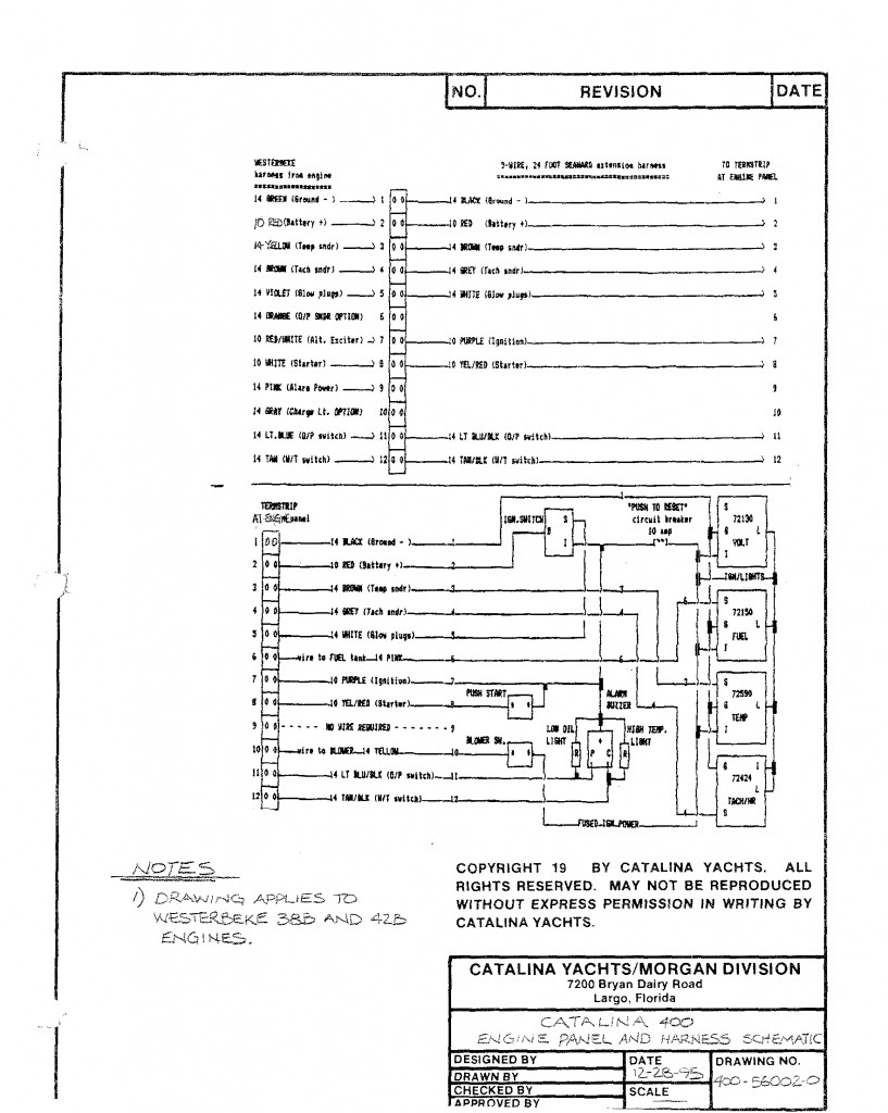
Westerbeke 42 B Engine Wiring Diagram

Title:Westerbeke 42 B Engine Wiring Diagram
Author:Warren Elliott
Date: 11/1/2003
Hull #: 44

Here is the wiring diagram for the WesterBeke 42B. This engine was also used on the Catalina 400.


You need to be logged in to see the rest of this content.  Catalina380-IA members, please login.

To join please fill out a membership application (Association->Membership Application) and send a check to the address on the form.

Transmisssion Shift Lever

Title:         Transmisssion Shift Lever
Author:   Warren Elliott
Date:         11/1/2003
Hull #: 44


A few captains have reported failure of their shift lever; apparently none occurred at a critical time, so no damage ensued except perhaps to a few egos. It seems that the lever either became very loose or simply fell off, rendering shifting impossible. Quick crew action, including inventing a new handle in the form of vise-grip pliers, may have saved the day.

On checking my helm station, and receiving email comments from the manufacturer, Edson, I’m beginning to understand how these situations came about.

Here’s two Edson inputs. The first message refers to the particular problem and possible improvement. The second message address my questions: causes for the set screw becoming loose and a related issue: closeness of forward-shifted lever to the helm guard.

From: Edson Customer Service Sent: Tuesday, July 22, 2003 1:54 PM To: Warren

You need to be logged in to see the rest of this content.  Catalina380-IA members, please login.

To join please fill out a membership application (Association->Membership Application) and send a check to the address on the form.

Flexible Coupling for Drivetrain

Title:        Flexible Coupling for Drivetrain
Author:  Gordon R Croudace
Date:       8/12/2003
Hull #: 18

I am the owner of a Catalina 380C [“”Cahuilla””, Hull no.18], based in Sydney, Australia. I recently fitted a flexible coupling between the transmission and the propeller shaft. As it has made such a dramatic difference in terms of virtually eliminating vibration, reducing noise transmission through the hull and the impact of gear engagement, it has prompted me to recommend this relatively inexpensive and easy-to-fit mod to all owners. In fact, it surprises me that the flexible coupling is not fitted as standard equipment to all Catalina yachts.

The flexible coupling purchased is a product of R&D Drivetrain Solutions in Lynnwood, WA. USA. [ www.flexible-coupling.com]. It is available through PYI Inc. [ www.pyiinc.com. ] The model number of the flexible coupling fitted is 910-001. It is designed to be bolted between the transmission’s half coupling and

You need to be logged in to see the rest of this content.  Catalina380-IA members, please login.

To join please fill out a membership application (Association->Membership Application) and send a check to the address on the form.

Fuel Gauge Calibration

Fuel Gauge Calibration
Warren Elliott
2/1/2003
Hull #: 44

There have been a number of discussions on this topic on our Sailnet email discussion group. Most of you probably realize that our fuel tank is not a simple rectangular shape, especially in the vertical plane, and so the fuel gauge does not read accurately [our sender–the sensor in the tank–is a typical swinging-arm-with-float-type which is calibrated for a rectangular tank]. Rather it is tapered, from a depth of 11-1/2″ forward to an average of about 5″ aft. [It’s actually tapered in three directions].

In order to estimate what corrections to apply to our fuel gauge, I phoned our tank manufacturer [Ezell Industries], who supplied a dimensioned drawing [rather than measure my tank, a bit uncomfortable to do with our present winter set-up]. From this I was able to calculate- actually estimate- volume versus depth. To keep it relatively simple, I

You need to be logged in to see the rest of this content.  Catalina380-IA members, please login.

To join please fill out a membership application (Association->Membership Application) and send a check to the address on the form.